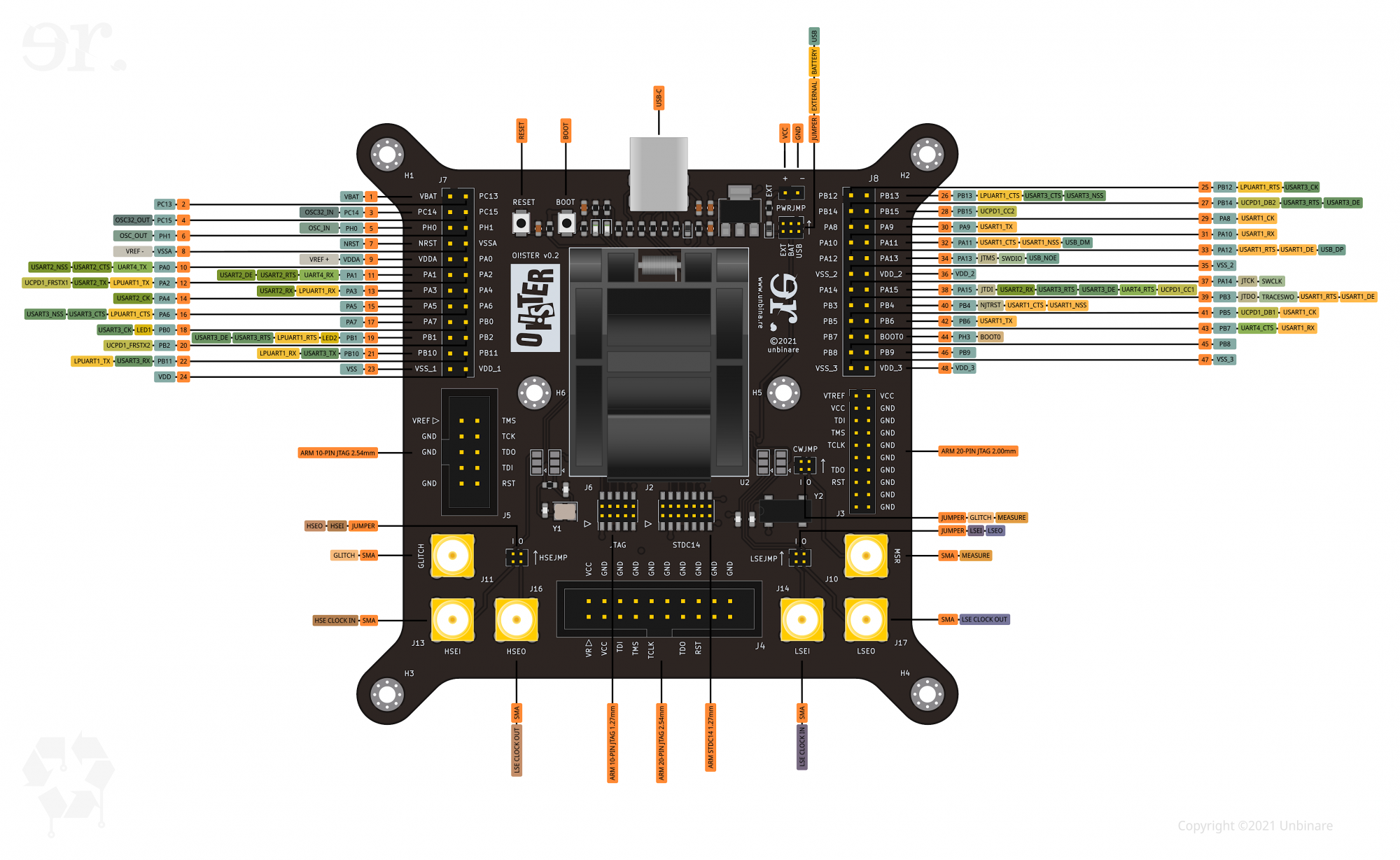
The OI!STER is an STM32L5 Target Board with a QFP48 clamshell socket aimed at debugging and glitching salvaged MCUs. The board can be powered via USB-C, a 2032 coin cell battery on the back of the board or an external power suppy. All pins are broken out in the 24-pin headers on either side at the top of the board. The OI!STER contains five debug headers, to support a wide range of debugging hardware such as a Hydrabus or a Black Magic Probe. It comes with six SMA connectors arranged in I/O pairs. One pair is dedicated to glitching the external LSE clock, another for glitching the external HSE clock and one pair for power analysis and fault injection with a Chipwhisperer. Each SMA connector can be bypassed by removing a small jumper. The OI!STER also has additional solder jumpers for the external clocks and each of the power traces to the MCU to allow for quick experimentation.
A full pinout and additional documentation is currently under development.
Debug Pinout
| Debug Pinout
|
|
| Pin
|
Function
|
Alternate Function
|
| 1
|
VBAT
|
| 2
|
PC13
|
| 3
|
PC14
|
OSC32_IN
|
| 4
|
PC15
|
OSC32_OUT
|
| 5
|
PH0
|
OSC_IN
|
| 6
|
PH1
|
OSC_OUT
|
| 7
|
NRST
|
| 8
|
VSSA
|
VREF-
|
| 9
|
VDDA
|
VREF+
|
| 10
|
PA0
|
UART4_TX
|
USART2_CTS
|
| 11
|
PA1
|
UART4_RX
|
USART2_RTS
|
| 12
|
PA2
|
LPUART1_TX
|
USART2_TX
|
| 13
|
PA3
|
LPUART1_RX
|
USART2_RX
|
| 14
|
PA4
|
USART2_CK
|
| 15
|
PA5
|
| 16
|
PA6
|
LPUART1_CTS
|
USART3_CTS
|
| 17
|
PA7
|
| 18
|
PB0
|
LED1
|
USART3_CK
|
| 19
|
PB1
|
LED2
|
LPUART1_RTS
|
USART3_RTS
|
| 20
|
PB2
|
| 21
|
PB10
|
LPUART1_RX
|
USART3_TX
|
| 22
|
PB11
|
LPUART1_TX
|
USART3_RX
|
| 23
|
VSS
|
| 24
|
VDD
|
| 25
|
PB12
|
USART3_CK
|
LPUART1_RTS
|
| 26
|
PB13
|
USART3_CTS
|
LPUART1_CTS
|
| 27
|
PB14
|
USART3_RTS
|
| 28
|
PB15
|
| 29
|
PA8
|
USART1_CK
|
| 30
|
PA9
|
USART1_TX
|
| 31
|
PA10
|
USART1_RX
|
| 32
|
PA11
|
USART1_CTS
|
USB_DM
|
| 33
|
PA12
|
USART1_RTS
|
USB_DP
|
| 34
|
PA13
|
JTMS
|
SWDIO
|
USB_NOE
|
| 35
|
VSS_2
|
| 36
|
VDD_2
|
| 37
|
PA14
|
JTCK
|
SWCLK
|
| 38
|
PA15
|
JTDI
|
USART2_RX
|
USART3_RTS
|
UART4_RTS
|
| 39
|
PB3
|
JTDO
|
TRACESWO
|
USART1_RTS
|
| 40
|
PB4
|
NJTRST
|
USART1_CTS
|
UART5_RTS
|
| 41
|
PB5
|
USART1_CK
|
UART5_CTS
|
| 42
|
PB6
|
USART1_TX
|
| 43
|
PB7
|
USART1_RX
|
UART4_CTS
|
| 44
|
PH3
|
BOOT0
|
| 45
|
PB8
|
| 46
|
PB9
|
| 47
|
VSS_3
|
| 48
|
VDD_3
|
Peripheral Pinout
| Peripheral Pinout
|
|
|
| Pin
|
Function
|
Alternate Function
|
| 1
|
VBAT
|
| 2
|
PC13
|
| 3
|
PC14
|
| 4
|
PC15
|
| 5
|
PH0
|
| 6
|
PH1
|
| 7
|
NRST
|
| 8
|
VSSA
|
| 9
|
VDDA
|
| 10
|
PA0
|
| 11
|
PA1
|
I2C1_SMBA
|
SPI1_SCK
|
OCTOSPI1_DQS
|
| 12
|
PA2
|
OCTOSPI1_NCS
|
| 13
|
PA3
|
OCTOSPI1_CLK
|
| 14
|
PA4
|
SPI1_NSS
|
SPI3_NSS
|
OCTOSPI1_NCS
|
| 15
|
PA5
|
SPI1_SCK
|
| 16
|
PA6
|
SPI1_MISO
|
OCTOSPI1_IO3
|
| 17
|
PA7
|
I2C3_SCL
|
SPI1_MOSI
|
OCTOSPI1_IO2
|
| 18
|
SPI1_NSS
|
OCTOSPI1_IO1
|
| 19
|
PB1
|
OCTOSPI1_IO0
|
| 20
|
PB2
|
I2C3_SMBA
|
OCTOSPI1_DQS
|
| 21
|
PB10
|
I2C2_SCL
|
I2C4_SCL
|
SPI2_SCK
|
OCTOSPI1_CLK
|
| 22
|
PB11
|
I2C2_SDA
|
I2C4_SDA
|
OCTOSPI1_NCS
|
| 23
|
VSS
|
| 24
|
VDD
|
| 25
|
PB12
|
USART3_CK
|
LPUART1_RTS
|
| 26
|
PB13
|
USART3_CTS
|
LPUART1_CTS
|
| 27
|
PB14
|
USART3_RTS
|
| 28
|
PB15
|
| 29
|
PA8
|
USART1_CK
|
| 30
|
PA9
|
USART1_TX
|
| 31
|
PA10
|
USART1_RX
|
| 32
|
PA11
|
USART1_CTS
|
USB_DM
|
| 33
|
PA12
|
USART1_RTS
|
USB_DP
|
| 34
|
PA13
|
JTMS
|
SWDIO
|
USB_NOE
|
| 35
|
VSS_2
|
| 36
|
VDD_2
|
| 37
|
PA14
|
JTCK
|
SWCLK
|
| 38
|
PA15
|
JTDI
|
USART2_RX
|
USART3_RTS
|
UART4_RTS
|
| 39
|
PB3
|
JTDO
|
TRACESWO
|
USART1_RTS
|
| 40
|
PB4
|
NJTRST
|
USART1_CTS
|
UART5_RTS
|
| 41
|
PB5
|
USART1_CK
|
UART5_CTS
|
| 42
|
PB6
|
USART1_TX
|
| 43
|
PB7
|
USART1_RX
|
UART4_CTS
|
| 44
|
PH3
|
BOOT0
|
| 45
|
PB8
|
| 46
|
PB9
|
| 47
|
VSS_3
|
| 48
|
VDD_3
|


